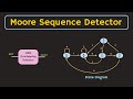
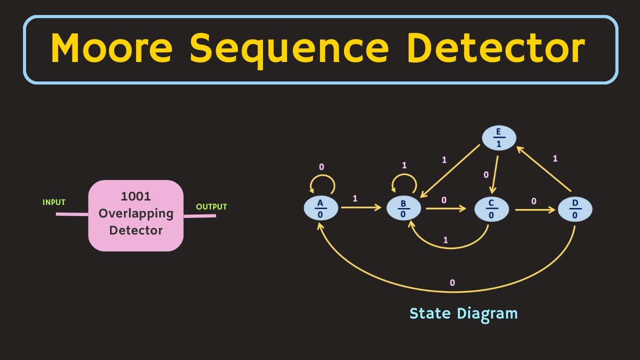
Design of Moore Sequence Detector (Overlapping and Non-overlapping) Explained with Simulation
In this video, the design of the Moore Sequence Detector (Overlapping and Non-overlapping Sequence) is explained through an example of a 1001 sequence detec...
ALL ABOUT ELECTRONICS
115.5K views • Jul 8, 2023
About this video
In this video, the design of the Moore Sequence Detector (Overlapping and Non-overlapping Sequence) is explained through an example of a 1001 sequence detector. And the working of the designed circuit is verified using the simulations. In the later part of the video, the ASM chart is also explained briefly and the demonstration of a Non-overlapping sequence detector using the ASM chart is shown in the Deeds Circuit Simulator.
Simulation Software used in the video: Deeds Digital Circuit Simulator
The link for the other useful videos related to Finite State Machine:
1) What is Finite State Machine? Mealy and Moore Machine Explained.
https://youtu.be/kb-Ww8HaHuE
2) How to Draw a State Transition Diagram | Analysis of Clocked Sequential Circuits
https://youtu.be/zVJiQZnMXxo
3) State Reduction and State Assignment in the State Diagram
https://youtu.be/qq7moL5ueNQ
4) Mealy Sequence Detector Explained:
https://youtu.be/PbjntQf3sGc
5) Sequential Circuits (Playlist):
https://www.youtube.com/playlist?list=PLwjK_iyK4LLCCpnnybEztvRqxpMyfgarS
The steps of designing the Finite State Machine :
1) Define the purpose of the Machine in simple words or in the form of a Block Diagram. Define the inputs and outputs of the FSM. It should be realizable using a finite number of memory elements.
2) Draw a State Transition Diagram
3) Draw a State Table
4) Remove the redundant states from the state table
5) Select the Type of Flip-Flop (D, T, JK or SR) and draw the excitation table
6) Find the Boolean Function for each flip-flop in terms of state variables and inputs.
In a same manner, also find the output Boolean Function.
7) Draw and Implement the Logic Circuit.
Chapters:
0:00 Introduction
0:53 Design of Moore Sequence Detector (1001 Overlapping Sequence)
15:17 Design of Moore Sequence Detector (1001 Non-overlapping Sequence)
16:58 Simulation of Overlapping Sequence Detector
19:02 Simulation of Non-Overlapping Sequence Detector using ASM chart
This video will be helpful to all the students of science and engineering in learning, how to design the Finite State Machine and how to design the Moore Sequence Detector (Overlapping and Non-Overlapping sequence detector).
#allaboutelectronics
#digitalelectronics
#finitestatemachine
#moore
Support the channel through a membership program:
https://www.youtube.com/channel/UCBkOVp1Cqz4MR0LYR8vKpZg/join
--------------------------------------------------------------------------------------------------
Follow my second channel:
https://www.youtube.com/channel/UCGA2TO8ylVqFHpucwn_6Jlw
Follow me on Facebook:
https://www.facebook.com/ALLABOUTELECRONICS/
Follow me on Instagram:
https://www.instagram.com/all_about.electronics/
--------------------------------------------------------------------------------------------------
Music Credit: http://www.bensound.com
Simulation Software used in the video: Deeds Digital Circuit Simulator
The link for the other useful videos related to Finite State Machine:
1) What is Finite State Machine? Mealy and Moore Machine Explained.
https://youtu.be/kb-Ww8HaHuE
2) How to Draw a State Transition Diagram | Analysis of Clocked Sequential Circuits
https://youtu.be/zVJiQZnMXxo
3) State Reduction and State Assignment in the State Diagram
https://youtu.be/qq7moL5ueNQ
4) Mealy Sequence Detector Explained:
https://youtu.be/PbjntQf3sGc
5) Sequential Circuits (Playlist):
https://www.youtube.com/playlist?list=PLwjK_iyK4LLCCpnnybEztvRqxpMyfgarS
The steps of designing the Finite State Machine :
1) Define the purpose of the Machine in simple words or in the form of a Block Diagram. Define the inputs and outputs of the FSM. It should be realizable using a finite number of memory elements.
2) Draw a State Transition Diagram
3) Draw a State Table
4) Remove the redundant states from the state table
5) Select the Type of Flip-Flop (D, T, JK or SR) and draw the excitation table
6) Find the Boolean Function for each flip-flop in terms of state variables and inputs.
In a same manner, also find the output Boolean Function.
7) Draw and Implement the Logic Circuit.
Chapters:
0:00 Introduction
0:53 Design of Moore Sequence Detector (1001 Overlapping Sequence)
15:17 Design of Moore Sequence Detector (1001 Non-overlapping Sequence)
16:58 Simulation of Overlapping Sequence Detector
19:02 Simulation of Non-Overlapping Sequence Detector using ASM chart
This video will be helpful to all the students of science and engineering in learning, how to design the Finite State Machine and how to design the Moore Sequence Detector (Overlapping and Non-Overlapping sequence detector).
#allaboutelectronics
#digitalelectronics
#finitestatemachine
#moore
Support the channel through a membership program:
https://www.youtube.com/channel/UCBkOVp1Cqz4MR0LYR8vKpZg/join
--------------------------------------------------------------------------------------------------
Follow my second channel:
https://www.youtube.com/channel/UCGA2TO8ylVqFHpucwn_6Jlw
Follow me on Facebook:
https://www.facebook.com/ALLABOUTELECRONICS/
Follow me on Instagram:
https://www.instagram.com/all_about.electronics/
--------------------------------------------------------------------------------------------------
Music Credit: http://www.bensound.com
Tags and Topics
Browse our collection to discover more content in these categories.
Video Information
Views
115.5K
Likes
1.2K
Duration
23:47
Published
Jul 8, 2023
User Reviews
4.4
(23) Related Trending Topics
LIVE TRENDSRelated trending topics. Click any trend to explore more videos.