Delta VFD & 3-Phase Motor Wiring Diagram ⚙️
Detailed wiring diagram for Delta VFD and 3-phase motor control, including MCCB 400V 3P connections and components.

Riyansh Electrical
129.2K views • Jul 17, 2025
About this video
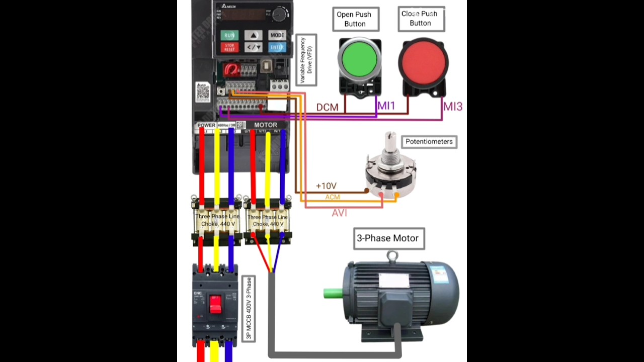
Components and Connections:
3P MCCB 400V 3-Phase:
This is a 3-phase Molded Case Circuit Breaker, providing overcurrent protection for the entire system.
Three Phase Line Choke, 440V:
Two line chokes are shown, likely used for smoothing the input current to the VFD and reducing harmonics.
Variable Frequency Drive (VFD):
The central control unit, regulating the speed and torque of the 3-phase motor.
Power Input: Connected from the line chokes (R, S, T) to the VFD's power input terminals.
Motor Output: Connected from the VFD's motor output terminals (U, V, W) to the 3-phase motor.
Control Inputs:
Open Push Button & Close Push Button: These buttons are wired to the VFD's digital inputs (MI1 and MI3) and a common ground (DCM) to control motor start and stop.
Potentiometers: Connected to the VFD's analog input (ACM) and +10V, providing a variable voltage signal to control the motor's speed.
3-Phase Motor:
The motor is connected to the VFD's output terminals.
#vfd #wiringdiagram #youtubeshorts #electrical
https://youtube.com/shorts/cUAe1AKUCqg?si=BIp2hsC443bdMAB2
https://youtu.be/y2_fmD9b9lg?si=rLIwwzSnEAS3xhmM
https://youtu.be/X3ufLN6YysU?si=5SSEEXk_PmIkamGf
Video Information
Views
129.2K
Likes
823
Duration
0:12
Published
Jul 17, 2025
User Reviews
4.2
(25) Related Trending Topics
LIVE TRENDSRelated trending topics. Click any trend to explore more videos.
No specific trending topics match this video yet.
Explore All Trends